How an incline works
Inclines have been part of the industrial and railway infrastructure for a very long time being frequently used to move material between differing levels, often from a quarry or point of manufacture to a dispatch point or a location where good could be transferred for onward shipment.
In out local area inclines were used at place like:-
Calstock
Kit Hill
Morewellham
Gunnislake Clitters Mine
As well as at Wilminstone Quarry and Lee Moor.
Inclines were no only constructed for industrial use, the Victorians built many for passenger uses particularly to gain easy access to a beach and the sea at such places as:-
Babbacombe
Lynton – Lynmouth
and of cause Bournmouth
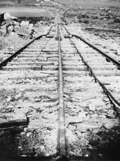
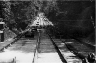
Above Left. Looking down the Kit Hill incline, this incline like Calstock used a common centre rail at the top. The cable can be seen between the right hand track therefore the right hand wagon is at the bottom of the incline and the left hand wagon at the top, also note the rollers for the cable.
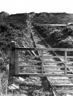
Above Right. The view from the bottom of Kit Hill incline, probably after closure, the cable can be seen below the gate on top if the rail
Industrial inclines were a cheap and easy method of moving material between levels. Early inclines were often built at quarries and usually consisted of one single line track, normally narrow gauge, laid on a bank so that wagons could be lowered by a rope or hauled up the bank by a horse or sometimes a stationary steam engine. These inclines were usually temporary and were frequently moved or extended as quarrying progressed.
More permanent inclines (like the Calstock, Kit Hill and Lee Moor inclines) worked on a balance system where one load descended the incline as another load was raised.
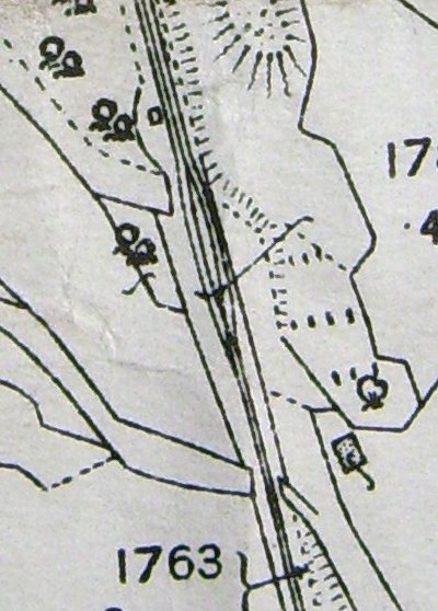
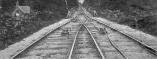
The simplest form of this type of incline consisted of two unconnected parallel lines but to save cost these were usually rationalises to one single line below the mid crossing point and two parallel tracks above the crossing point (as on the Lee Moor Tramway). The two tracks above the crossing point were often further rationalised by using one rail as common to both tracks (as at Calstock and Kit Hill).
Such arrangements of tracks were common where the rope linked pairs of rafts of wagons via a top rope drum. A consequence of this rope system means that the section below the loop only has a maximum of one rope on it at any one time, whereas the upper section has a minimum of one rope on it at any one time.
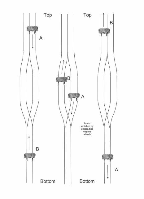
The other consequence of this arrangement is that the top tracks were used alternatively each trip as up and down tracks - i.e. the next load down uses the track the last load up used. This stops the ropes getting crossed over. It also means the point at the lower end of the loop is automatically set by each movement - a downward raft pushes the blades over which are then in the right position for the next upward movement.
How an incline works
Start with a wagon at the top of the incline and one at the bottom. Get a rope slightly longer than the length of the incline (or a cable)
Attach one end of a rope to the top wagon, run it round a pulley (or similar) at the top that can be braked, then attach the other end to the wagon at the bottom.
Then as one wagon ascends it is balanced by the weight of the descending carriage, so little power is required to get the wagons moving or braked.. At the centre point of the incline you need a short length of double track so that the wagons can pass. If you have three rails on the incline you can arrange this by "splitting" the centre rail, and you do not need moving points.
Such inclines were usually arranged so that the weight of the descending wagon was a little greater than the ascending one, so that there was no need for external power to raise the ascending car. In the case of the Lynton-Lynmouth system the cars had tanks that were filled with water at the top of the incline and emptied at the bottom.
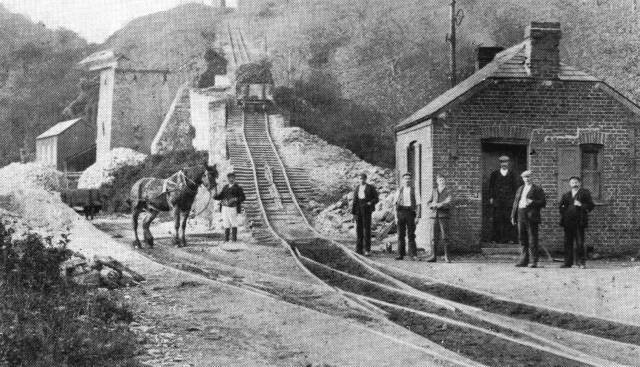
The bottom of Calstock incline, this incline was unusual as it was curved just below the half way point.
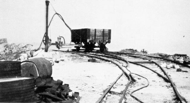
A wagon a t the top of Kit Hill incline. Most inclines of this type had some sort of system to prevent runaway wagons and to automatically apply a brake to the cable drum if a wagon inadvertently went over the top of the incline.
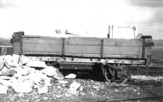
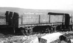
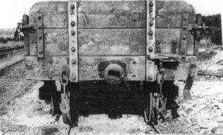
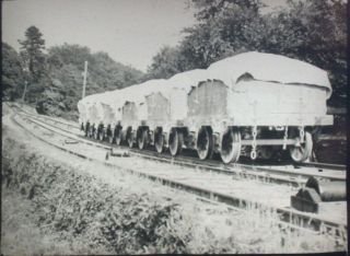
Most of the wagons used by the ECMR on the Calstock incline and the Kit Hill incline were built in local boat yards
Three pictures of wagons used on the Kit Hill incline
Calstock incline crossover point from 1906 OS map note the three lines above and two below the crossover
The Lee Moor Tramway was similar to the Calstock and Kit Hill inclines except that the line above the cross over point remained as two parallel lines
A close look at the half way crossing point on the Lee Moor Tramway, note the cable and roller
A raft of 6 wagons descending a Lee Moor incline
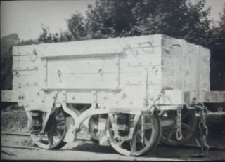
A Lee Moor Tramway wagon, far more substantial than those used at Calstock and Kit Hill
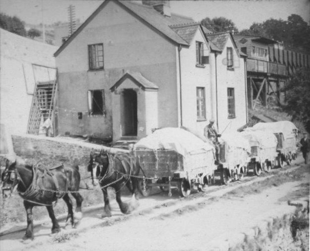
A cracking photograph of the Lee Moor Tramway on the outskirts of Plymouth
